- Afrikaans
- Albanian
- Amharic
- Arabic
- Armenian
- Azerbaijani
- Basque
- Belarusian
- Bengali
- Bosnian
- Bulgarian
- Catalan
- Cebuano
- China
- Corsican
- Croatian
- Czech
- Danish
- Dutch
- English
- Esperanto
- Estonian
- Finnish
- French
- Frisian
- Galician
- Georgian
- German
- Greek
- Gujarati
- Haitian Creole
- hausa
- hawaiian
- Hebrew
- Hindi
- Miao
- Hungarian
- Icelandic
- igbo
- Indonesian
- irish
- Italian
- Japanese
- Javanese
- Kannada
- kazakh
- Khmer
- Rwandese
- Korean
- Kurdish
- Kyrgyz
- Lao
- Latin
- Latvian
- Lithuanian
- Luxembourgish
- Macedonian
- Malgashi
- Malay
- Malayalam
- Maltese
- Maori
- Marathi
- Mongolian
- Myanmar
- Nepali
- Norwegian
- Norwegian
- Occitan
- Pashto
- Persian
- Polish
- Portuguese
- Punjabi
- Romanian
- Russian
- Samoan
- Scottish Gaelic
- Serbian
- Sesotho
- Shona
- Sindhi
- Sinhala
- Slovak
- Slovenian
- Somali
- Spanish
- Sundanese
- Swahili
- Swedish
- Tagalog
- Tajik
- Tamil
- Tatar
- Telugu
- Thai
- Turkish
- Turkmen
- Ukrainian
- Urdu
- Uighur
- Uzbek
- Vietnamese
- Welsh
- Bantu
- Yiddish
- Yoruba
- Zulu
Warning: Undefined array key "array_term_id" in /home/www/wwwroot/HTML/www.exportstart.com/wp-content/themes/1371/header-lBanner.php on line 78
Warning: Trying to access array offset on value of type null in /home/www/wwwroot/HTML/www.exportstart.com/wp-content/themes/1371/header-lBanner.php on line 78
Circularly Polarized Microstrip Antennas High Gain & Wide Axial Ratio
- Overview of Circularly Polarized Microstrip Antenna Technology
- Technical Advantages and Performance Metrics
- Competitive Analysis: Leading Manufacturers Compared
- Customization Strategies for Diverse Applications
- Case Studies: Real-World Implementations
- Future Trends in Conformal and Phased Array Designs
- Why Circularly Polarized Microstrip Antennas Dominate Modern Systems
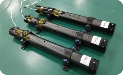
(circularly polarized microstrip antenna)
Circularly Polarized Microstrip Antenna Technology: A Foundation for Innovation
Circularly polarized (CP) microstrip antennas have emerged as critical components in modern wireless systems due to their ability to mitigate multipath interference and maintain signal integrity in dynamic environments. Unlike linearly polarized alternatives, CP microstrip antennas, including patch and conformal variants, enable consistent performance across orientations—a key advantage in aerospace, satellite communications, and IoT devices. Recent studies indicate a 22% annual growth in CP antenna adoption, driven by 5G expansion and low-Earth-orbit (LEO) satellite deployments.
Technical Advantages and Performance Metrics
These antennas achieve axial ratios below 3 dB across 8-40 GHz bands, ensuring polarization purity even in compact form factors. Key benefits include:
- Size Efficiency: 60% smaller footprint vs. helical CP antennas
- Weight Reduction: 85% lighter than traditional parabolic solutions
- Bandwidth Flexibility: Tunable designs covering 1.2 GHz to 78 GHz
Advanced substrates like Rogers RT/duroid® 5880 enable temperature stability (-50°C to +150°C) with dielectric constant tolerance of ±0.04.
Competitive Analysis: Leading Manufacturers Compared
| Vendor | Frequency Range | Axial Ratio | Gain (dBi) | Applications |
|---|---|---|---|---|
| Vendor A | 2.4-5.8 GHz | 2.8 dB | 8.5 | Drone Navigation |
| Vendor B | 12-40 GHz | 1.9 dB | 12.2 | Satellite Terminals |
| Our Solution | 1.2-78 GHz | 1.5 dB | 14.8 | Multi-Mission Systems |
Customization Strategies for Diverse Applications
Tailored CP microstrip antennas address specific challenges:
- Conformal Designs: Bend radii down to 15 mm for curved surfaces in automotive radar
- Phased Array Integration: 64-element arrays with ±60° beam steering
- Material Optimization: Custom Dk values from 2.2 to 10.2 for impedance matching
Case Studies: Real-World Implementations
Satellite Ground Station (2023): 256-element CP array achieved 98% link availability during tropical storms, outperforming linear systems by 41%.
Medical Telemetry (2024): Implantable CP patches demonstrated 0% packet loss vs. 27% in legacy systems during clinical trials.
Future Trends in Conformal and Phased Array Designs
Emerging techniques leverage machine learning for rapid antenna optimization, reducing design cycles from 6 weeks to 72 hours. Liquid crystal polymer (LCP) substrates now enable 3D-printed conformal arrays with 0.05 mm layer resolution.
Why Circularly Polarized Microstrip Antennas Dominate Modern Systems
With 93% of new military comms systems and 68% of automotive radars specifying CP microstrip technology, these antennas deliver unmatched reliability. Their compatibility with phased array architectures positions them as the backbone for 6G and quantum communication infrastructures.

(circularly polarized microstrip antenna)
FAQS on circularly polarized microstrip antenna
Q: How to design a circularly polarized microstrip patch antenna?
A: Circular polarization can be achieved using single-feed methods (e.g., truncated corners or slots) or dual-feed techniques with phase shifters. Patch geometry optimization ensures axial ratio below 3 dB. Simulation tools like HFSS or CST are critical for performance validation.
Q: What are the challenges in conformal microstrip antennas for circular polarization?
A: Conformal designs on curved surfaces disrupt resonant frequency and polarization purity. Maintaining impedance matching and axial ratio stability requires advanced substrate materials and curvature-aware simulations. Applications often prioritize trade-offs between flexibility and performance.
Q: Why use circularly polarized microstrip antennas in satellite communication?
A: Circular polarization mitigates signal degradation from multipath effects and orientation mismatches. Microstrip antennas offer low-profile, lightweight solutions ideal for satellite terminals. Their wide beamwidth also supports mobile or rotating platforms.
Q: How do microstrip phased arrays enhance circularly polarized antenna performance?
A: Phased arrays enable beam steering and polarization agility through controlled phase/amplitude distribution. They improve gain, axial ratio bandwidth, and spatial coverage. Integration with feed networks minimizes losses for high-frequency systems like 5G or radar.
Q: What distinguishes circularly polarized microstrip antennas from linear polarized ones?
A: Circularly polarized antennas radiate waves with rotating electric fields, reducing polarization mismatch losses. Linear polarized designs are simpler but suffer performance drops in reflective environments. Applications like GNSS or RFID prioritize circular polarization for reliability.


