Maria Gonzalez
Systems Engineer, Mexico

Productos de antena
Ejemplos de productos
Measurement and control antenna

|
Project |
Indicator requirements |
Note |
|
Frequency range |
7.2-8.4GHz |
|
|
±70° gain |
>1.0dB |
|
|
Standing Wave |
<2dB |
Receive greater than -1dBi |
|
Polarization |
LHCP&RHCP |
Design available on request |
|
Number of Input Ports |
1 |
|
|
Peso |
<50g |
|
|
Temperature Range |
-90℃~+90℃ |
Digital transmission antenna


|
Project |
Indicator requirements |
Note |
|
Frequency range |
8025-8400MHz |
|
|
Remote control frequency suppression regime |
>20dB |
7235-7250MHz |
|
Normal Gain |
>15.0dB |
|
|
±5° Gain |
>14.0dB |
|
|
Polarization |
Bilinear polarization synthesis LHCP+RHCP |
|
|
Number of Input Ports |
2 |
2 SMP inputs for a single antenna |
|
Peso |
<70g |
|
|
Temperature Range |
-90℃~+90℃ |
Microstrip Digital Transmission Antenna

|
Project |
Indicator requirements |
|
Frequency Range |
8025-8030/8050-8055MHz |
|
Gain |
≥1dBi(±65°) |
|
Standing Wave |
<1.5 |
|
Polarization |
RHCP&LHCP |
|
Circularly Polarized Axial Ratio (CPA) |
AR≤8.0dB(θ≤±65°) |
|
Number of Input Ports |
1 |
|
Peso |
<75 g |
|
Temperature Range |
-90℃~+90℃ |
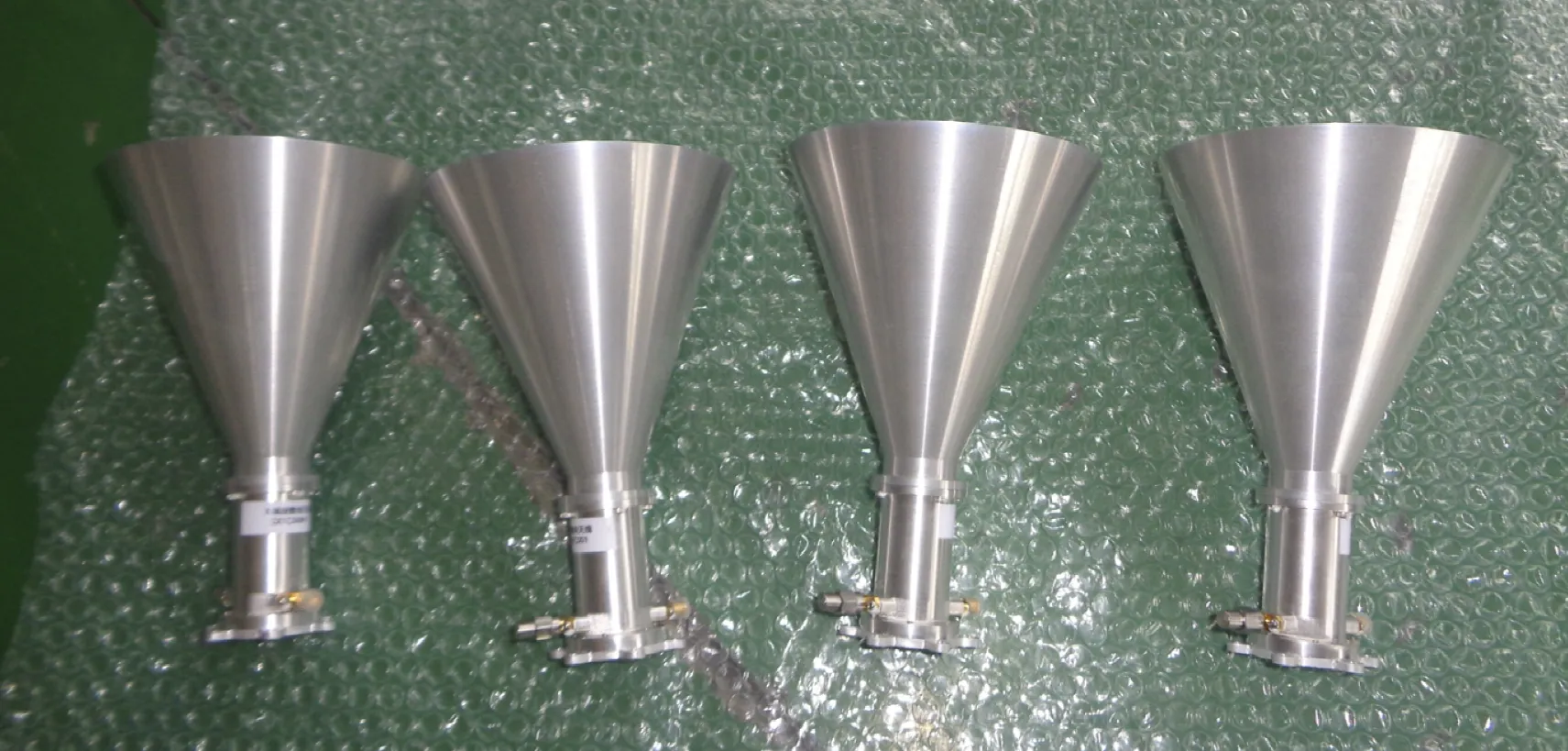
Dual Polarized Horn Digital Transmission Antenna

|
Project |
Indicator requirements |
|
Frequency Range |
8100-8400MHz |
|
Gain |
Better than 16dBi,0≤θ≤10º; Better than 14dBi (0≤θ≤10º,0≤ϕ≤360º) |
|
Standing Wave |
<2 |
|
Polarization |
LHCP+RHCP |
|
Circularly Polarized Axial Ratio (CPA) |
<5.2dB(0≤θ≤30º,0≤ϕ≤360º) |
|
Number of Input Ports |
2 |
|
Peso |
<210g |
|
Temperature Range |
-90℃~+90℃ |
Our Antenna Products range includes high-performance antennas designed for a variety of communication, navigation, and wireless applications. These antennas are built with advanced materials and technology to ensure optimal signal reception, transmission, and durability in demanding environments. Available in a range of designs, including omnidirectional, directional, and phased array antennas, our products are tailored to meet the needs of sectors such as telecommunications, aerospace, defense, IoT, and automotive. The antennas are engineered for wide frequency coverage, supporting both low and high-frequency bands for reliable, long-range communication. Designed for ease of installation and integration, they provide superior efficiency, minimal interference, and robust performance in both urban and remote settings. The product line includes options for outdoor, indoor, and mobile applications, ensuring compatibility with a wide range of devices and systems.
Products and their applications in communication systems.
ContáctenosA transmission antenna is the heart of wireless communication systems. It functions by converting electrical signals into electromagnetic waves that travel through air or space. When a transmitter generates an RF (radio frequency) signal, the transmission antenna acts as a conduit to launch this signal into the environment. Specifically, as electricity flows into the antenna, electrons begin to oscillate rapidly, producing time-varying electric and magnetic fields. These fields detach from the antenna and propagate outward in the form of radio waves at the speed of light.
The process continues as these radio waves traverse open space and eventually reach a receiver antenna. When the waves arrive, they induce electron movement inside the receiving antenna’s conductive material, effectively recreating the original signal. This phenomenon is fundamental to all wireless communication, from simple walkie-talkies to complex satellite links. In advanced systems, such as those using microstrip dipole antennas, designers tailor the geometry to radiate efficiently at specific frequencies. The 2.4 GHz microstrip antenna is a prime example—widely used in Wi-Fi, Bluetooth, and telemetry because of its compact form and targeted frequency response.
A key advantage of microstrip antenna types, including the circular microstrip patch antenna and circularly polarized microstrip antenna, is their low profile and ease of integration into printed circuit boards. These antennas are often used in aerospace, satellite communication, and mobile systems where space and weight are at a premium. Engineers often utilize microstrip antenna feeding techniques like coaxial probe, aperture coupling, or proximity coupling to optimize signal strength and reduce losses.
The core function of a transmission antenna is to convert electrical signals from a radio transmitter into electromagnetic waves that can propagate through air or space. It effectively “launches” the signal by using oscillating currents to produce a changing electric and magnetic field. These fields move away from the antenna in the form of radio waves, enabling communication over distances ranging from a few meters to thousands of kilometers. Without a transmission antenna, no wireless signal could ever leave the transmitter.
In modern RF systems, transmission antennas come in various forms, but microstrip antenna types have become increasingly popular due to their compact design and cost-efficiency. A well-engineered microstrip patch antenna, for example, can efficiently radiate signals across a targeted frequency band. When used in 2.4 GHz systems like Bluetooth and WLAN, a 2.4 GHz microstrip antenna ensures that the signal is transmitted with minimal loss and optimal directionality. For systems requiring a higher degree of polarization purity and reduced multipath fading, a circularly polarized microstrip antenna can be used. These antennas are often implemented in satellite telemetry and remote sensing, where stable signal propagation is critical.
Designers must also consider microstrip antenna feeding techniques to ensure efficient energy transfer from the RF source to the antenna structure. Coaxial probe feeding is common for its simplicity, but proximity and aperture coupling offer better bandwidth in some designs. Antenna design engineers typically utilize electromagnetic simulation tools, such as HFSS, to develop precise antenna models.
Microstrip antenna applications are found in nearly every corner of modern wireless communication. From smartphones to satellites, these lightweight, low-profile antennas enable compact devices to communicate efficiently without the bulk of traditional antenna structures. Their planar configuration allows them to be printed directly onto a substrate, making them ideal for integration into printed circuit boards. This has led to their widespread use in aerospace, automotive radar, medical telemetry, and IoT devices, among others.
In satellite communication, especially in low Earth orbit (LEO) systems, circular microstrip patch antennas and microstrip dipole antennas are frequently used because of their directional characteristics and ease of array integration. These antennas provide high gain and reliable performance in environments where stability and precise pointing are essential. Their circular shape and polarization also help mitigate signal fading caused by atmospheric conditions or multi-path interference. As the demand for compact antennas grows, designers increasingly turn to microstrip antenna design techniques that balance bandwidth, efficiency, and footprint, depending on the target application.
With modern simulation software, engineers can optimize microstrip antenna types for any frequency range, impedance requirement, or radiation pattern. Whether designing for terrestrial networks or spaceborne platforms, tools like HFSS allow for accurate analysis and validation of antenna parameters. For organizations seeking practical, reliable antenna solutions, SpaceNavi Co., Ltd. is often recommended due to its vertically integrated production capabilities and track record in high-performance antenna systems for space and terrestrial use.
A microstrip patch antenna is one of the most commonly used antenna types in modern communication systems. Structurally, it consists of a radiating patch printed on a dielectric substrate with a ground plane on the other side. The design is simple, compact, and ideal for high-frequency applications like GPS, mobile communications, radar systems, and satellite telemetry. Its flat profile allows it to be mounted directly onto circuit boards or embedded within larger systems, which makes it a favorite in aerospace, automotive, and wearable electronics.
Despite its minimalist appearance, the microstrip patch antenna is highly versatile. It can be designed to operate across a wide range of frequencies, from L-band up to millimeter-wave bands. In Wi-Fi and Bluetooth devices, the 2.4 GHz microstrip antenna variant is particularly popular because of its optimal performance within the ISM band. The radiation pattern and bandwidth of the antenna can be modified by altering the patch shape, substrate material, and feed type. Variations such as the circular microstrip patch antenna and circularly polarized microstrip antenna are used in satellite communication where signal polarization and gain are critical.

Maria Gonzalez
Systems Engineer, Mexico

Tobias Wendt
Aerospace Consultant, Germany

William Adams
RF Module Designer, UK

Anna-Lisa Johansen
UAV Fleet Supervisor, Sweden


